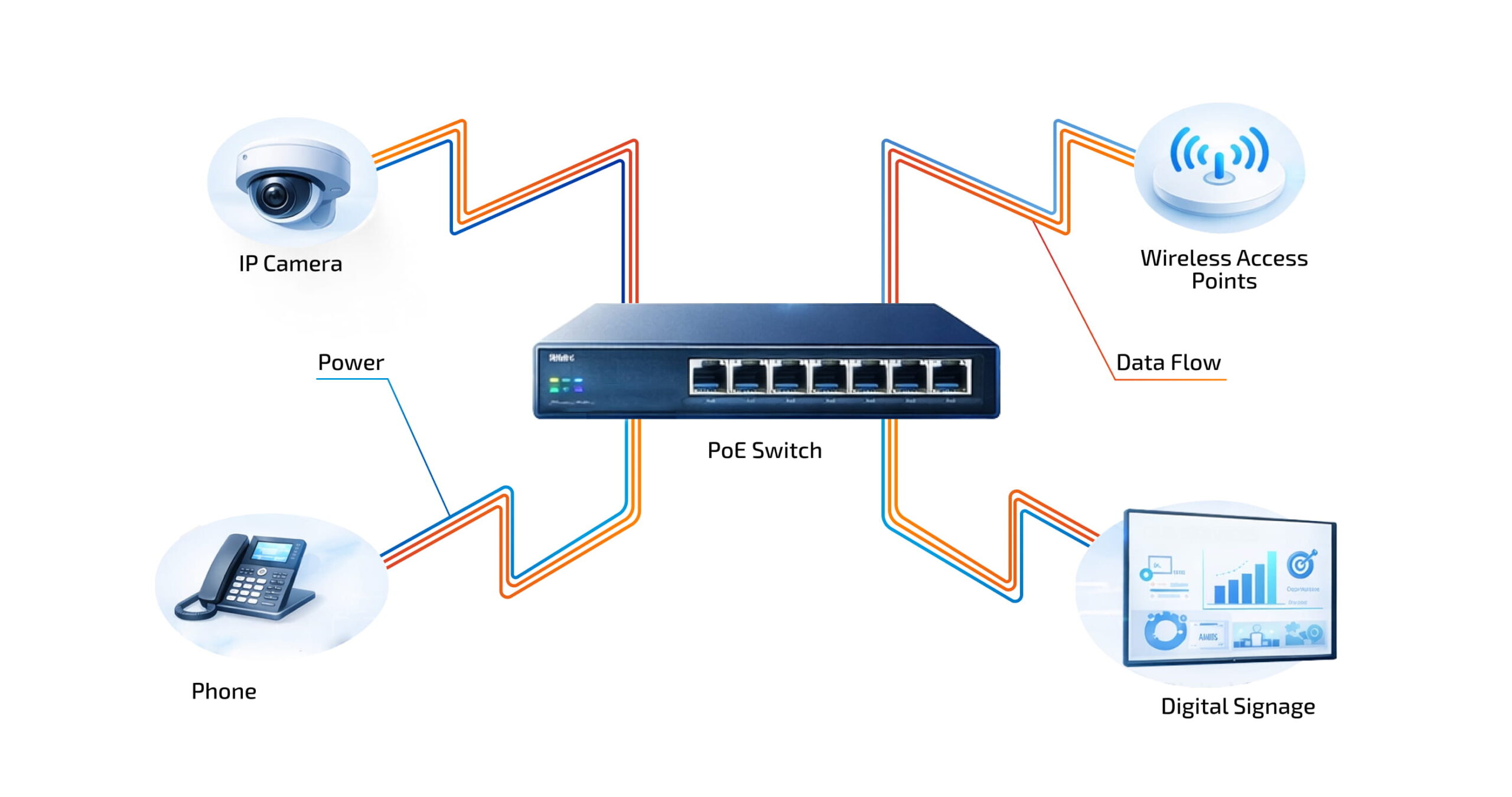
Modern networks demand intelligent power delivery to endpoints scattered across buildings, campuses, and data centers. Power over Ethernet (PoE) has evolved from a convenience for VoIP phones into a critical infrastructure technology powering everything from WiFi 6/7 access points to intelligent LED lighting systems. Understanding the nuances of PoE standards is the foundation for building scalable, efficient, and future-proof networks.
The Evolution of Power Over Ethernet: A Standards Journey
The IEEE 802.3 PoE standards represent a deliberate progression, each generation designed to meet escalating power demands while maintaining backward compatibility. This evolutionary approach ensures that modern switches can safely power devices manufactured two decades ago alongside cutting-edge equipment.
IEEE 802.3af (Type 1 PoE): The Foundation
Ratified in 2003, the 802.3af standard revolutionized network design by formalizing power delivery over Ethernet cables. The innovation stemmed from a simple observation: 10/100Base-TX Ethernet used only two of four available pairs in Category 5 cables, leaving pairs available for power transmission.
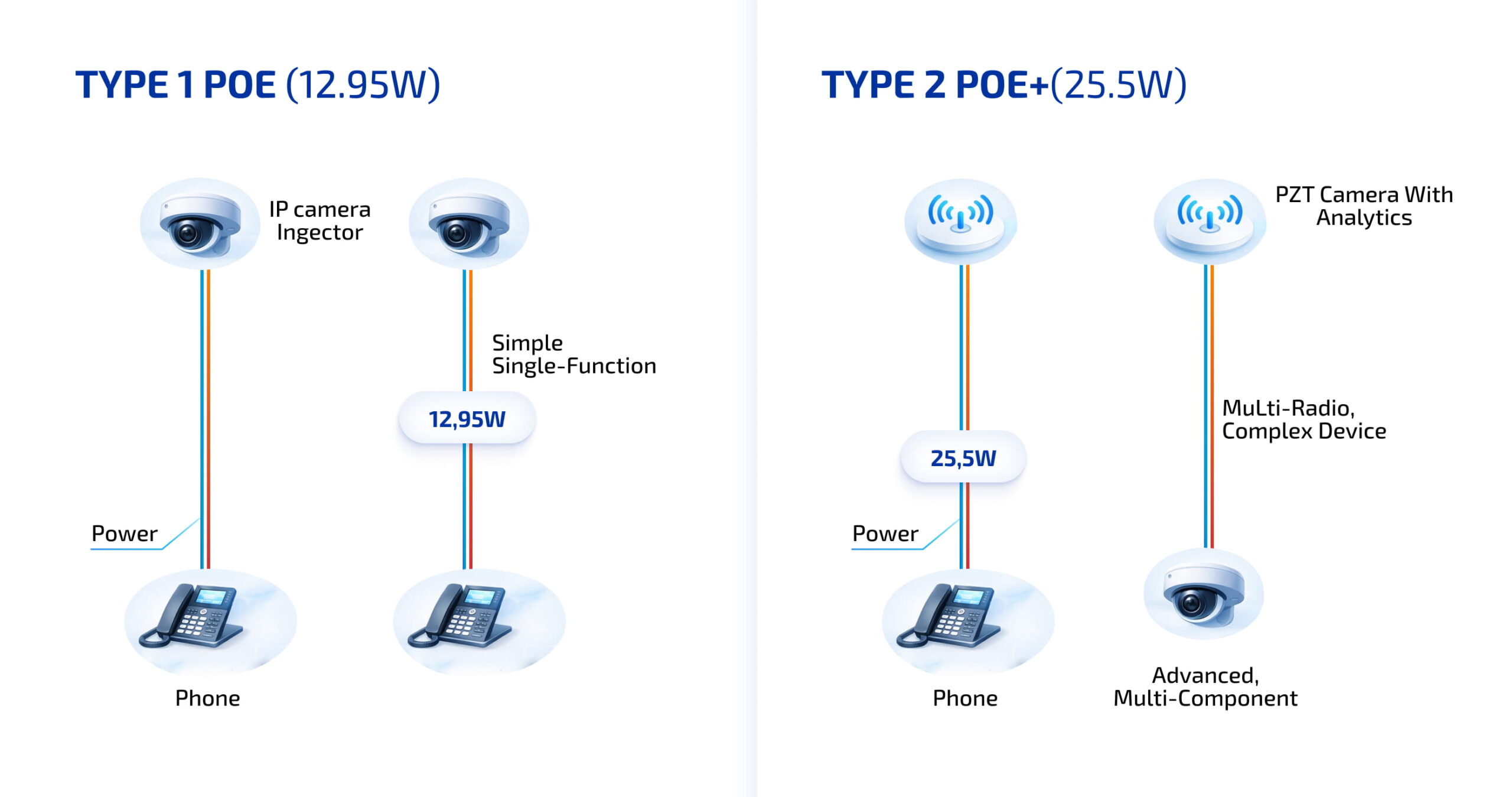
Type 1 PoE delivers:
- Maximum 15.4W at the Power Sourcing Equipment (PSE)
- Guaranteed 12.95W at the Powered Device (PD) after transmission losses
- Operating voltage range: 44V to 57V DC
- Power delivery over 2 pairs
While the 12.95W ceiling became restrictive as devices evolved, Type 1 remains highly relevant for low-power applications including basic IP cameras, simple VoIP phones, environmental sensors, and access control systems. The economic advantage is significant: lower power requirements enable switches with smaller power supplies and reduced thermal management complexity, lowering cost per port.
IEEE 802.3at (Type 2 PoE+): Meeting Growing Demands
As network endpoints integrated LCD screens, PTZ motors, and video conferencing capabilities, the 802.3af standard proved insufficient. The 2009 ratification of 802.3at (PoE+) doubled available power to 30W at the PSE, delivering 25.5W to the powered device after transmission losses.
Type 2 PoE+ delivers:
- Maximum 30 W at the Power Sourcing Equipment (PSE)
- Guaranteed 25.5 W at the Powered Device (PD) after transmission losses
- Operating voltage range: ~50 V to 57 V DC
- Power delivery over 2 pairs
Crucially, PoE+ maintains full backward compatibility through sophisticated power negotiation. An 802.3at-compliant switch automatically detects Type 1 devices and provides appropriate power levels, preventing damage while enabling infrastructure upgrades without forklift replacements. This generation introduced advanced classification mechanisms allowing devices to communicate precise wattage requirements, optimizing power budget allocation across switch ports.
PoE+ has become the enterprise networking baseline, supporting advanced WiFi 5 and early WiFi 6 access points, high-resolution IP cameras with video analytics, multi-line VoIP systems, and complex building automation equipment.
IEEE 802.3bt (PoE++): The High-Power Revolution
The 2018 ratification of IEEE 802.3bt represented the most significant leap in PoE capability. Often called PoE++, 4PPoE, or Ultra PoE, this standard introduced two new power classes and a fundamental architectural shift: utilizing all four twisted pairs for power delivery rather than just two.
Type 3 specifications:
- 60W at PSE
- 51W guaranteed at PD
- Primary applications: multi-radio WiFi 6 access points, advanced PTZ cameras, video conferencing systems
Type 4 specifications:
- 90-100W at PSE
- 71.3W guaranteed at PD
- Enables entirely new device classes: thin clients, large digital signage, intelligent LED building lighting
This power level fundamentally changes building design, eliminating dedicated AC power lines for an entire category of networked equipment. The implications for smart buildings, IoT deployments, and WiFi 7 infrastructure are profound.
| Feature | Type 1 (802.3af) | Type 2 (802.3at) | Type 3 (802.3bt) | Type 4 (802.3bt) |
|---|---|---|---|---|
| Max Power at PSE | 15.4W | 30.0W | 60.0W | 90-100W |
| Min Power at PD | 12.95W | 25.5W | 51.0W | 71.3W |
| Energized Pairs | 2–pair | 2–pair | 4–pair | 4–pair |
| Ratification Year | 2003 | 2009 | 2018 | 2018 |
The Intelligence Behind PoE: Active Negotiation vs. Passive Power
A critical distinction separates professional PoE implementations from hazardous shortcuts: the difference between standardized active PoE and non-standard passive PoE. This distinction isn’t merely academic – it’s the difference between safe, reliable operation and potential equipment destruction.
The Three-Stage PoE Handshake
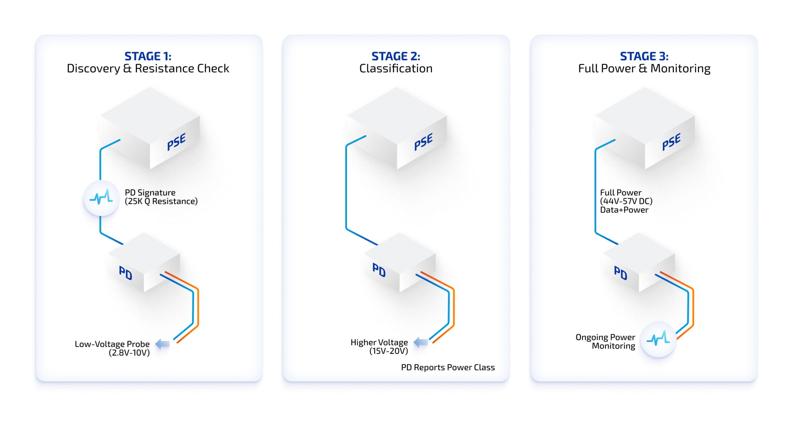
Standardized PoE employs a sophisticated detection and classification process before applying high-voltage power, ensuring compatibility and safety through three distinct stages:
1. Discovery (Detection)
The PSE applies a low probing voltage (2.7V to 10.1V) to detect a valid PoE signature characterized by specific resistance of approximately 25kΩ (allowable range: 19kΩ to 26.5kΩ). This ensures power isn’t sent to non-PoE devices that could be damaged by unexpected voltage.
2. Classification
Once a valid PD is detected, the PSE increases voltage (typically 14.5V to 20.5V) to determine the device’s power requirements. The PD responds by drawing specific current corresponding to a power class (0 through 8), enabling precise power allocation.
3. Operation
After successful classification, the PSE supplies full operating voltage while continuously monitoring the connection through a Maintain Power Signature (MPS). If the PD disconnects or ceases drawing minimum power, the PSE immediately cuts power to prevent hazards.
The Danger of Passive PoE
Passive PoE presents a stark contrast: it provides constant, fixed voltage (typically 24V or 48V) to Ethernet cables regardless of the attached device’s requirements. There is no negotiation, no safety protocol, and no device detection. Connecting a non-PoE device or a PoE device with different voltage requirements to a passive PoE port can result in immediate, permanent hardware damage.
While passive PoE appears in some legacy proprietary systems, professional infrastructure deployments should exclusively employ IEEE-compliant active PoE for safety and reliability.
Advanced Power Management: LLDP and Dynamic Allocation
Physical layer classification provides initial power allocation, but sophisticated networks employ Data Link Layer classification for real-time optimization. This is achieved through the Link Layer Discovery Protocol (LLDP) and its Media Endpoint Discovery (LLDP-MED) extensions.
LLDP enables powered devices to communicate exact wattage needs in 0.1W increments. For example, a Class 4 device (30W rated) consuming only 18W during regular operation can advertise a lower operational power requirement (18W) via LLDP. The switch can then reclaim the unused 12W for other ports, optimizing the total power budget.
This dynamic allocation proves vital for large-scale deployments like smart buildings where managing aggregate switch power budgets prevents overloads and port throttling. In Cisco ecosystems, the Cisco Discovery Protocol (CDP) serves similar functions, though modern Catalyst hardware supports standard LLDP for multi-vendor compatibility.
The Physics of High-Power PoE: Thermal Considerations
As PoE wattage increases, the physical limitations of copper cabling become critical design constraints. Electrical current through conductors inevitably generates heat due to resistance – a phenomenon described by Joule’s Law. For high-power applications like 802.3bt Type 4, which can push nearly 1 Ampere per pair, thermal management becomes paramount.
Cable Selection Imperatives
Conductor Material:
Only pure copper conductors should be used for PoE. Copper-Clad Aluminum (CCA) cables exhibit approximately 60% higher resistance than pure copper, leading to significantly greater heat generation and failure risk under load. CCA cables violate TIA – 568 standards and frequently cause “burnt cable” incidents in high-power installations.
Wire Gauge:
Thicker wires possess lower resistance. While 24 AWG is common for Cat 5e, 23 AWG represents the standard for Cat 6 and 6a. Higher-grade cables like Cat 6a are essential for PoE++ to reduce energy waste and maintain safe internal temperatures.
Shielding:
Shielded Twisted Pair (STP) cables generally offer superior heat dissipation compared to Unshielded Twisted Pair (UTP) because the metallic foil acts as a heat sink, distributing thermal load more evenly across the cable jacket.
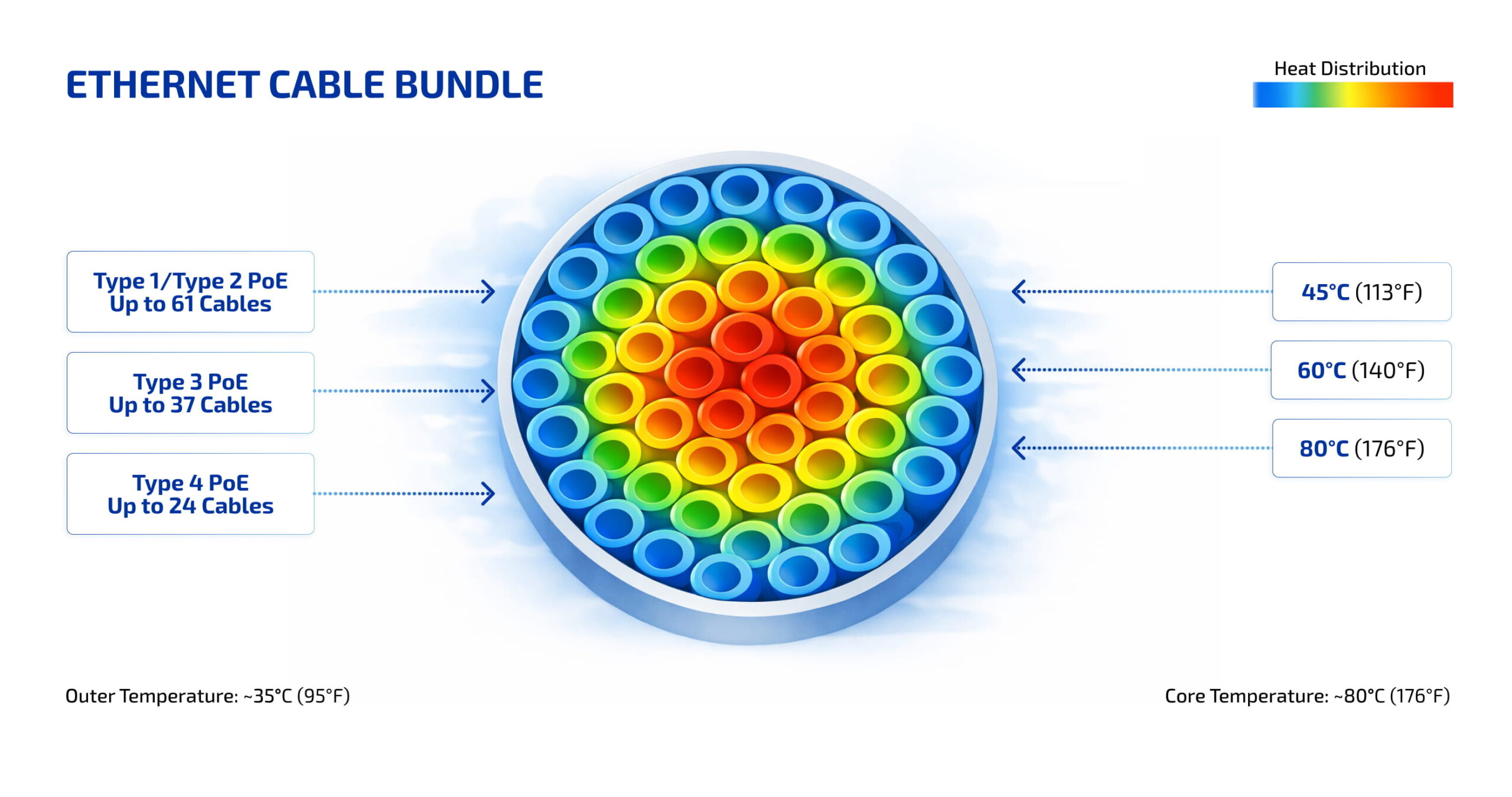
Cable Bundling and Heat Accumulation
Professional installations rarely feature isolated cable runs – cables are bundled in trays or conduits where heat accumulates in bundle centers. TIA guidelines recommend maximum 15°C temperature rise within bundle centers. As power levels increase, maximum allowable bundle sizes decrease proportionally. For instance, while 100 Category 6a cables can be bundled for standard PoE+, that bundle should be reduced or split for 802.3bt deployments to prevent excessive heat buildup.
Building the Open Networking Future with SONiC
As organizations deploy increasingly sophisticated PoE infrastructure to power WiFi 7, IoT sensors, and intelligent building systems, the underlying network operating system becomes equally critical. Traditional vendor lock-in limits flexibility, inflates costs, and complicates multi-vendor integration – challenges that open networking solutions directly address.
Download our white paper to learn more about SONiC's capabilities and unlock its potential for your business. Discover how SONiC can revolutionize your network infrastructure, offering unparalleled flexibility, scalability, and cost optimization.
PLVision: Specialized Expertise for Digital Sovereignty
Realizing digital sovereignty requires specialized expertise, and PLVision delivers precisely that. With proven experience in open, disaggregated networking, PLVision can develop production-ready, hardened Community SONiC images specifically designed for data center environments, addressing common pain points in deploying and managing network operating systems.
These images eliminate vendor lock-in, ensure compatibility with white-box hardware, and remove the burden of juggling multiple vendor-specific NOS versions. Rigorous testing guarantees seamless integration of Community SONiC into existing infrastructure, simplifies rollouts, and reduces deployment risk.
Custom SONiC Distributions: Tailored for Your Needs
For organizations requiring even greater flexibility, PLVision offers custom SONiC distributions tailored to specific use cases. While SONiC’s complexity demands in-house expertise for customization and maintenance, a bespoke build delivers cost efficiency, vendor neutrality, and freedom from subscription fees. Supporting high-speed switching (100G/400G/800G), advanced protocols like BGP, VXLAN, and EVPN, and seamless multivendor integration, these distributions grant full ownership and agile scalability.
Considering a switch to open-source networking?
Explore the reasons to choose an open-source NOS like SONiC, along with a breakdown of the Total Cost of Ownership (TCO) for both proprietary and open-source solutions.
Telecom providers can leverage custom SONiC distributions designed for carrier-grade requirements, addressing limitations of the community edition by incorporating critical features for telco use cases. PLVision enables faster, more cost-effective development aligned with sustainability, support, and budget goals.
SONiC Lite: Optimized for DC, Campus, and Edge
For campus and edge environments, PLVision’s SONiC Lite streamlines enterprise-grade features into a lightweight NOS optimized for management and access switches. By removing unnecessary modules, it runs efficiently on simpler, cost-effective hardware without compromising performance or reliability – perfect for PoE-intensive deployments powering access points, cameras, and IoT devices across distributed locations.
SONiC Lite Solution Brief
- Comprehensive Overview for Decision Makers
- Technical Architecture and Deployment Models
- Technical Specifications & Features
- Complete Feature Set and Protocol Support
- Hardware Requirements and Compatibility Matrix
Active community leadership in SONiC and DentOS governing boards cements PLVision’s role in shaping open standards and ensures European needs for transparency, security, and vendor neutrality remain front and center in the development of next-generation network infrastructure.
Regulatory Compliance: NEC 2023 and Safety Standards
The safety implications of high-power PoE have driven significant updates in the National Electrical Code (NEC). The 2023 revision reflects a broader restructuring where limited-energy requirements have been reorganized into new articles to improve usability and reduce misapplication.
Article 725 and Limited Power Certification
NEC Article 725.144 specifically addresses the transmission of power and data. A significant development is the introduction of the “LP” (Limited Power) cable rating. Cables marked with an LP suffix (e.g., CL2P-LP) have undergone specialized testing in large, tightly packed bundles enclosed in conduit to ensure they can carry specified current without exceeding temperature ratings.
For cables without an LP suffix, installers must adhere to NEC Table 725.144, which provides maximum allowable ampacity based on the number of cables in a bundle and conductor gauge. For example, a 23 AWG cable rated at 75°C can safely carry 0.7A in bundles of 1 to 7 cables, but that ampacity drops significantly as bundle size increases to 192 cables. For installations exceeding 192 cables, the NEC requires ampacity determination by qualified personnel under engineering supervision.
Practical Installation Best Practices
Beyond regulatory compliance, industry best practices emphasize:
- Cable Management: Use Velcro straps instead of zip ties to prevent cable crushing and allow better airflow
- Separation: Maintain at least 2 inches distance from AC power lines or use separate conduits to prevent EMI and cross-thermal effects
- Temperature Derating: In environments exceeding 30°C (86°F), derate allowable current and cable lengths to prevent overheating
Strategic Planning for PoE Infrastructure Deployment
Implementing high-performance PoE infrastructure requires holistic planning that balances power budgets, thermal management, and future scalability.
Calculating Total Power Budget
Before selecting switches, architects must calculate total power demand for all connected PDs. This isn’t simply adding nominal values – it requires accounting for peak usage and operating environment. For instance, a PTZ camera may draw only 15W while idle but spike to 28W when motors and heaters activate. Apply a 20% safety buffer to total calculated demand to ensure adequate PSE capacity.
Future-Proofing for WiFi 7 and Beyond
The transition to WiFi 7 (802.11be) is the primary driver for 802.3bt adoption. These access points feature multiple high-frequency radios and multigigabit backhauls, often requiring 30W to 60W for full functionality. Deploying Category 6a cabling and 802.3bt-compliant switches today avoids costly “rip-and-replace” upgrade cycles in three to five years.
SONiC Lite Free Demo
Implement SONiC on cost-effective platforms with SONiC Lite
Environment-Specific Considerations
Equipment selection must reflect the physical environment. Standard office deployments typically utilize managed PoE+ switches. However, harsh industrial environments or high-density AV setups may require specialized hardware designed for extreme temperatures, humidity, and vibration, ensuring reliability under demanding conditions.
Conclusion: Powering Tomorrow’s Connected Infrastructure
The evolution of Power over Ethernet from the modest 13W of Type 1 to the robust 90W capability of Type 4 marks a fundamental transformation in how we conceptualize building power infrastructure. This convergence provides unparalleled flexibility, cost savings, and centralized management while introducing new complexities in cabling, thermal dynamics, and regulatory compliance.
For network designers, understanding the distinctions between PoE standards forms the foundation of reliable system architecture. While 802.3af and 802.3at continue serving legacy VoIP and surveillance needs, the emergence of 802.3bt (PoE++) catalyzes the next generation of smart infrastructure – from WiFi 7 access points to networked LED lighting and ubiquitous IoT sensors.
By embracing open networking principles, organizations can build networks that are not only powerful but also vendor-neutral and future-proof. The integration of intelligent power negotiation through LLDP, resilient continuity features, and robust cabling practices compliant with NEC standards will define enterprise network success as we advance toward increasingly connected infrastructure.
Ready to transform your network infrastructure with open, vendor-neutral solutions?